


MODEL “190RB”
Medium Duty Roller Bed Belt Conveyor
Applications / Features:
- Packing
- Inspecting
- Sorting
- Assembling
- Testing
- Transporting Horizontally or on Incline
Online Resources:
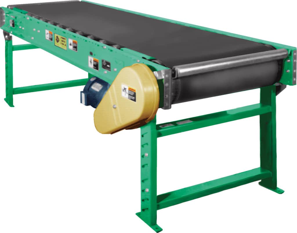
Belt – 12″, 18″, 24″, 30″, 36″, 42″ and 48″ Black PVC 120 belt. (For Optional Equipment, Weight Specifications, and Engineering Line Drawings, please see catalog pages, above). STANDARD SPECIFICATIONS
Bed– Roller bed with 1.9″ diameter galvanized steel rollers. Rollers spaced on 6″ centers. Rollers mounted in 7″ deep x 12 gauge powder painted formed steel channel frames. Frames bolted together with butt couplings and floor supports.
X-Bracing – Frame squaring device supplied on conveyors 40 feet and longer for every other bed section. X-bracing insures good product and belt tracking.
Drive Pulley – 8″ diameter crowned and fully lagged, 1-7/16″ shaft.
Tail Pulley – 4″ diameter crowned supplied through 30″ wide belts. 6″ diameter crowned supplied for 36″ and wider belts. 4″ diameter pulley has 1-3/16″ diameter shaft; 6″ diameter pulley has 1-7/16″ diameter shaft turned down on ends to 1-3/16″ diameter.
Pop-Out Roller– 1.9″ diameter roller, Iocated at drive pulley and tail pulley.
Snub Roller– 2-1/2″ diameter adjustable roller, Iocated directly behind drive pulley, 2″ diameter located behind tail pulley.
Return Rollers – 1.9″ diameter adjustable on 10’0″ centers.
Take-Up – Located at tail end, provides 12″ of belt take-up.
Bearings – Sealed-prelubricated with cast iron housings.
Floor Supports – Adjustable 31-1/2″ to 45-1/2″ from floor to top of belt.One support supplied at each end of conveyor and at each bed joint.
Speed Reducer – C-Face mounted heavy duty worm gear reducer.
Motor – 1/2 HP 230/460-3-60 TE motor.
Belt Speed – 60 FPM constant.
Capacity – 200 pounds per foot maximum. Not to exceed Load Capacity Chart.![]()
OPTIONAL EQUIPMENT
Belt – Nitrile (white or black) with smooth top cover, Black PVC rough top, Brown Nitrile rough top. Special belts on application.
Roller Centers – 1.9″ diameter galvanized steel rollers spaced on
3″, 4- 1⁄2″, 9″ or 12″ centers.
Guard Rails – Adjustable channel, continuous channel, or solid steel guard rails available.
Floor Supports – Lower or higher than standard. Castered supports with 4″ diameter or 6″ diameter rigid or swivel casters.
Ceiling Hangers – 1⁄2″ diameter threaded rods 8 feet long with locking nuts and mounting hardware. Other lengths are available.
Nose-Over – Adjustable single or double nose-over provides smooth transfer from incline to horizontal. See https://automatedconveyors.com/?page_id=589 for details.
Side Mounted Drive – End drive mounted to side of conveyor section. Specify side. Minimum elevation – 10″.
Center Drive – Mounted below conveyor bed section. Can be placed most anywhere in conveyor length.
Auxiliary Take-Up – Mounted below conveyor bed section. Can be placed most anywhere in conveyor length.
Motor – Single phase, energy efficient, explosion proof, etc. Other HP available.
Belt Speed – Constant and variable belt speeds available.
Electrical Controls – Magnetic starters and push button stations; manual motor starters with overload protection, others.
Power Feeder – Separate belt section with (2) MD-6 (28- 1⁄2″ to 42- 1⁄2″ adjustable) supports. Feeder driven by roller chain from
main conveyor. Auxiliary take-up required on inclined conveyor. Integral feeder available.

