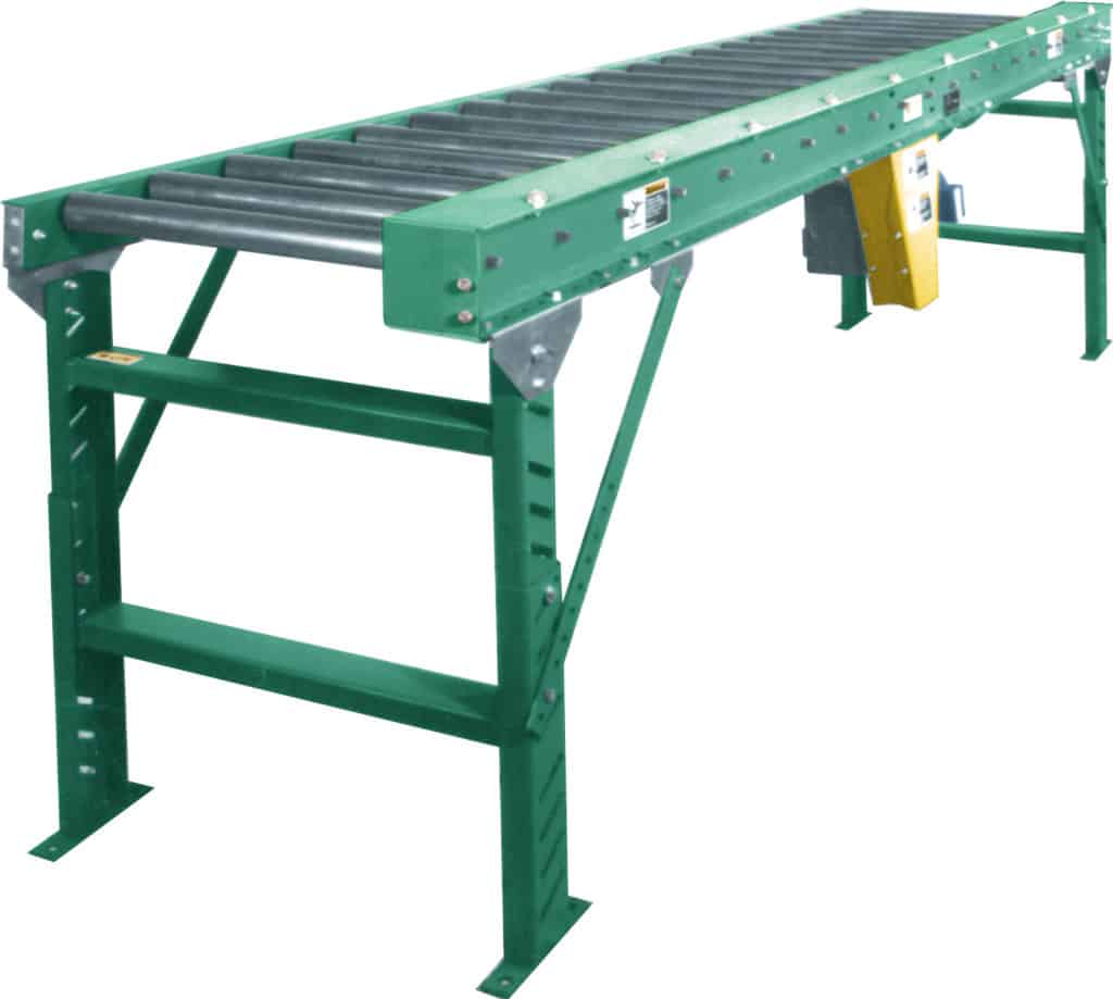
MODEL “22CRR”
Medium Duty Chain Driven Live Roller

Applications / Features:
- Wash Down Operations
- Oily Conditions
- Positive Drive-no Belt Slippage
Online Resources:
STANDARD SPECIFICATIONS
Drive Chain – No. 40 roller chain on straight sections.
Bed– Conveying surface width 14″, 16″, 18″, 24″, 28″, and 34″. 3-1/2″ x 1-1/2″ x 10 gauge powder painted formed steel channel on one side, 5″ x 1-1/2″ x 10 gauge formed steel channel on chain drive side. Sections are bolted together with butt couplings and floor supports.
Tread Rollers– 2″ diameter x 12 gauge steel with #40 sprockets welded to roller tube, 7/16″ hex shafts. Rollers spaced on 4″, 6″, 8″ and 12″ centers. Rollers are roller to roller driven.
Chain Guard– Chain guard is mounted to frame to totally enclose drive chain.
Center Drive – Mounted underneath conveyor, near center of section. Can be placed most anywhere in conveyor length. Specify.
Floor Supports – Adjustable 28″ to 42″ from floor to top of rollers. One support supplied at each end of conveyor and at each bed joint.
Speed Reducer – C-Face mounted heavy duty worm gear reducer.
Motor – 1/2 HP 230/460/3/60 TE motor.
Roller Speed– 60 FPM constant.
Capacity– Maximum load 150 Ibs. per foot;maximum unit load 500 pounds. Not to exceed Load Capacity Chart.
(For Optional Equipment, Weight Specifications, and Engineering Line Drawings, please see catalog pages, above).
(Optional colors available at extra cost)
OPTIONAL EQUIPMENT
Guard Rails-Adjustable channel,continuous channel,or solid steel guard rails available.
Floor Supports – Lower or higher supports are available. Minimum elevation 17-1⁄2″ from floor to top of rollers. Ceiling Hangers – 1⁄2″ diameter threaded rods 8 feet long with locking nuts and mounting hardware. Other lengths are available.
Ceiling Hangers– 1/2″ diameter threaded rods 8 feet long with locking nuts and mounting hardware. Other lengths are available.
Side Mounted Drive – Drive mounted to side of conveyor section. Specify side. Minimum elevation – 7″ from floor to top of rollers.
Rollers Set Low – Tread rollers mounted low in 4-1⁄2″ x 10 gauge formed steel channel frame to form 3⁄4″ high guard rails.
Motor – Single phase, energy efficient, explosion proof, etc. Other HP available.
Roller Speed – Constant and variable roller speeds available.
Electrical Controls – Magnetic starters and push button stations; manual motor starters with overload protection, others.


