


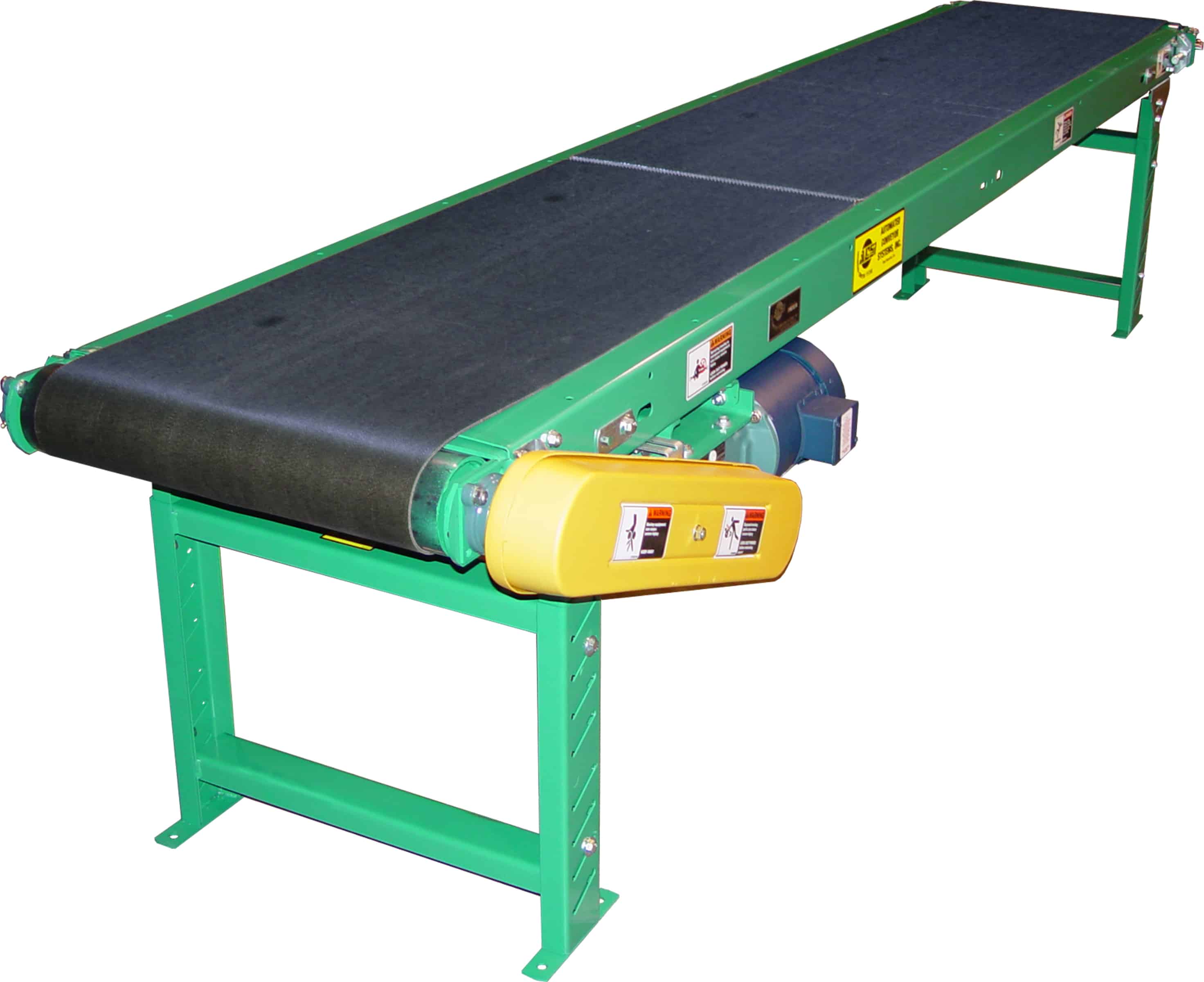
MODEL “LPB”
Medium Duty Slider Bed Belt Conveyor
Applications / Features:
- Packing
- Inspecting
- Sorting
- Assembly
- Testing
- Transporting
Online Resources:
STANDARD SPECIFICATIONS
Belt – 8″, 12″, 18″, 20″, 24″ and 30″ Black PVC 120 Belt.
Bed – 12 gauge powder painted formed steel, 4″ deep. Bed sections are 5 feet and 10 feet long, bolted together with spice plates and floor supports.
Tail Pulley – 4″ diameter crowned with 1-3/16″ diameter shaft.
Drive Pulley – 4″ diameter and 8″ diameter crowned and fully lagged. 4″ diameter pulley with 1-3/16″ diameter shaft, 8″ diameter pulley with 1-7/16″ diameter shaft.
Snub Roller – 2″ diameter (for 4″ diameter drive pulley), 2-1/2″ diameter (for 8″ diameter drive pulley).
Return Roller – 1.9″ diameter adjustable on 10’0″ centers.
Floor Supports – Adjustable 28-1/2″ to 42-1/2″ from floor to top of belt. One support supplied at each end of conveyor and at each bed joint.
Take-Up – 6″ long screws located at tail pulley to provide belt tension.
Bearings – Sealed and pre-lubricated with cast iron housings.
Speed Reducer – C-Face mounted heavy duty worm gear reducer.
Motor – 1/2 HP 230/460-3-60 TE motor.
Belt Speed – 60 FPM constant.
Capacity – Maximum load per lineal foot of conveyor – 75 lbs. Not to exceed Load Capacity Chart (see catalog page).
(For Optional Equipment, Weight Specifications, and Engineering Line Drawings, please see catalog pages, above).
OPTIONAL EQUIPMENT
Belt – Nitrile (white or black) with smooth top cover, Black PVC rough top, Brown Nitrile rough top. Special belts on application.
Side Tables – 10″, 16″ or 22″ wide formed steel side tables provide 12″, 18″ or 24″ work area. Tables are supported by angles bolted to bed section.
Guard Rails – Adjustable channel, continuous channel, or solid steel guard rails available.
Floor Supports – Lower or higher than standard. Castered supports with 4″ diameter or 6″ diameter rigid or swivel casters.
Ceiling Hangers – 1⁄2″ diameter threaded rods 8 feet long with locking nuts and mounting hardware. Other lengths are available.
Gravity Conveyor Brackets – Adjustable bracket with 13⁄8″ diameter pop-out roller for attaching wheel or roller conveyor.
Nose-Over – Adjustable single or double nose-over provides smooth transfer from incline to horizontal. See drawing on page 96 for details.
Center Drive – Mounted below conveyor bed section. Can be placed most anywhere in conveyor length.
Side Mounted Drive – End drive mounted to side of conveyor section. Specify side. Minimum 6″ elevation with 4″ drive pulley, minimum 9″ elevation with 8″ drive pulley.
Overhead Drive – End drive mounted above conveyor. Specify clearance required.
Auxiliary Take-Up – Mounted below conveyor bed section. Can be placed most anywhere in conveyor length.
Motor – Single phase, energy efficient, explosion proof, etc. Other HP available.
Belt Speed – Constant and variable belt speeds available.
Electrical Controls – Magnetic starters and push button stations; manual motor starters with overload protection, others.

