


MODEL “TSB”
Trough Slider Bed Belt Conveyor
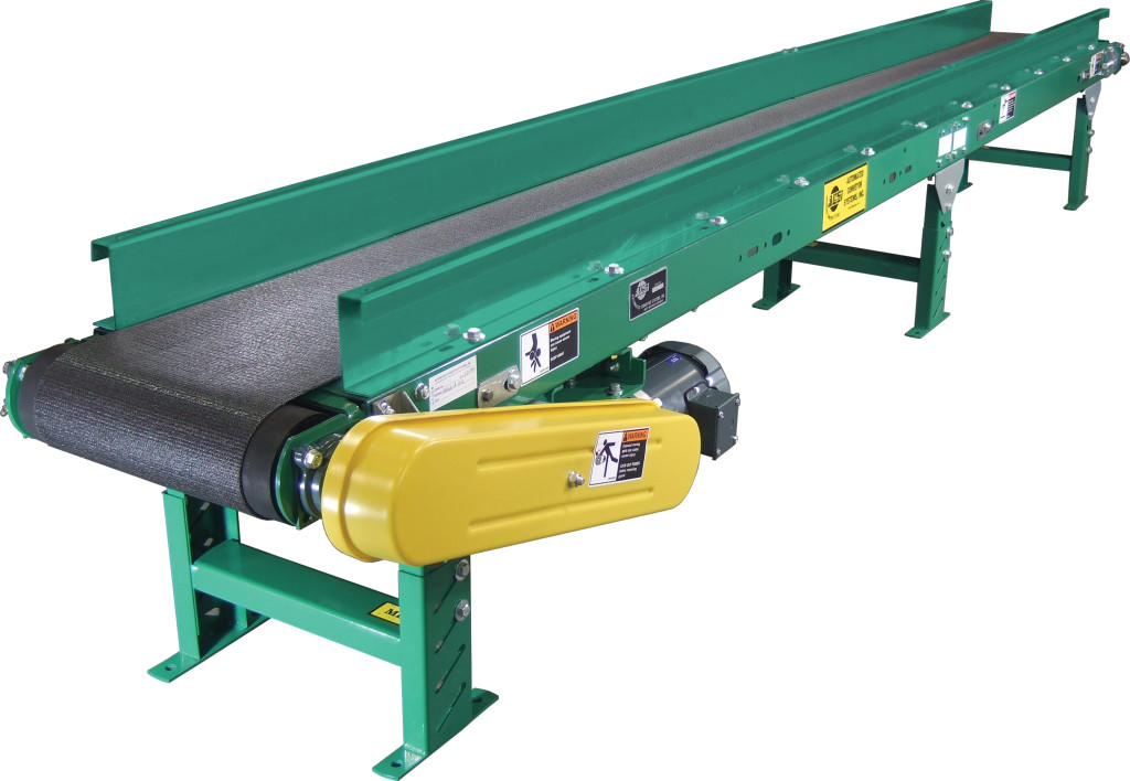
Applications / Features:
- Conveys Boxes, Bags, Cases, Loose Parts
- Built-in Guard Rails Allow Overhead Conveying
Online Resources:
STANDARD SPECIFICATIONS
Belt– 8″, 12″, 18″, 20″, 24″ and 30″ Black PVC 120 belt.
Bed – 12 gauge powder painted formed steel with 2-1⁄2″ high vertical sides bolted to top of bed. Standard sections are 5 and 10 feet long bolted together with floor supports and splice plates.
Tail Pulley – 4″ diameter crowned with 1-3⁄16″ diameter shaft.
Drive Pulley – 4″ diameter and 8″ diameter crowned and fully lagged. 4″ diameter pulley with 1-3⁄16″ diameter shaft, 8″ diameter pulley with 1-7⁄16″ diameter shaft.
Snub-Roller – 2″ diameter for 4″ diameter pulley, 2-1⁄2″ diameter for 8″ diameter pulley.
Return Idler – 1.9″ diameter adjustable, on 10’0″ centers.
Floor Supports – Adjustable 28-1⁄2″ to 42-1⁄2″ from floor to top of belt. One support supplied at each end of conveyor and at each bed joint.
Take-Up – 6″ long screws located at tail pulley to provide belt tension.
Bearings – Sealed pre-lubricated with cast iron housings.
Speed Reducer – C-Face mounted heavy duty worm gear reducer.
Motor – 1⁄2 HP 230/460-3-60 TE motor.
Belt Speed – 60 FPM constant.
Capacity – Maximum load per lineal foot of conveyor – 75 pounds. Not to exceed Load Capacity Chart.
(For Optional Equipment, Weight Specifications, and Engineering Line Drawings, please see catalog pages, above).
OPTIONAL EQUIPMENT
Belt – Nitrile (white or black), with smooth top cover, Black PVC rough top, Brown Nitrile rough top. Special belts on applications.
Guard Rail – Higher than 21⁄2″ vertical sides, 4″, 6″, 9″,to 12″ max.
Floor Supports – Lower or higher than standard. Castered supports with 4″ diameter or 6″ diameter rigid or swivel casters.
Ceiling Hangers – 1⁄2″ diameter threaded rods 8 feet long with locking nuts and mounting hardware. Other lengths are available.
Gravity Conveyor Brackets – Adjustable bracket, with 1-3⁄8″ diameter pop-out roller, for attaching wheel or roller conveyor.
Nose-Over – Adjustable single or double nose-over provides smooth transfer from incline to horizontal. See drawing on page 96 for details.
Center Drive – Mounted below conveyor or bed section. Can be placed most anywhere in conveyor length.
Side Mounted Drive – End drive mounted to side of conveyor section. Specify side. Minimum 6″ elevation with 4″ drive pulley, minimum 9”elevation with 8″ drive pulley.
Overhead Drive – End drive mounted above conveyor. Specify clearance required.
Auxiliary Take-Up – Mounted below conveyor bed section. Can be placed most anywhere in conveyor length.
Motor – Single phase, energy efficient, explosion proof, etc. Other HP available.
Belt Speed – Constant and variable belt speeds available.
Electrical Controls – Magnetic starters and push button stations; manual motor starters with overload protection, others.
Hugging Strip – Steel bars each side bolt to guard rail to prevent material from getting under belt. Must be used with a solid guard rail.
Troughing Attachment – Steel bars each side under belt form trough for handling loose material.

