


MODEL “SBT”
Slider Bed Trash Conveyor
Applications / Features:
- Adjustable floor supports
- Incline to 15′
- Guard rails
- Economical
Online Resources:
STANDARD SPECIFICATIONS
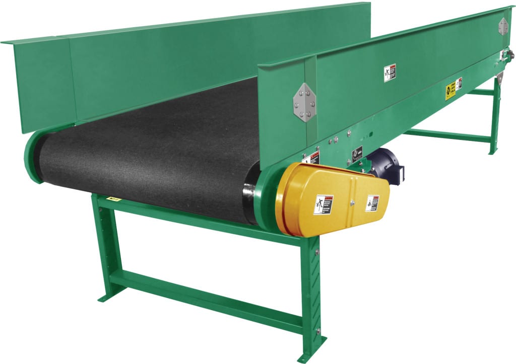
Bed – 5-1/2″ deep x 14 gauge powder painted formed steel channel frame. Bed sections are 10 feet and 5 feet long, bolted together with splice plates and floor supports.
Belt – 12″, 18″, 24″, 30″, 36″, 42″ and 48″ wide, black PVC 120, FS x FS.
Guard Rail – 6″ high x 16 gauge formed, powder painted steel on both sides, full length of bed sections.
Underside Guards – Formed 16 gauge pans full length of bed sections, removable, secured with TEK screws.
Tail Pulley – 4″ or 6″ diameter (see chart) crowned with 1-3/16″ diameter shaft.
Drive Pulley – 4″, 6″ and 8″ diameter crowned and fully lagged. 4″ and 6″ diameter pulleys have 1-3/16″ diameter shaft, 8″ diameter pulley has 1-7/16″ diameter shaft.
Snub Rollerr – 2″ diameter (for 4″ and 6″ diameter drive pulleys), 2-1/2″ diameter (for 8″ diameter drive pulley).
Return Rollers – 1.9″ diameter placed on 10′ centers.
Floor Supports – Adjustable 30″ to 44″ from floor to top of belt. One floor support provided at each end of conveyor and at each bed joint.
Take-Up – 6″ long screws located at tail pulley to provide belt tension.
Bearings – Sealed, prelubricated with cast iron housings.
Speed Reducer – C-Face mounted heavy duty worm gear reducer.
Motor – 1/2 HP 230/460-3-60 TE motor.
Capacity – 10 pounds per foot maximum live load. See Load Capacity Chart.
(For Optional Equipment, Weight Specifications, and Engineering Line Drawings, please see catalog pages, above).
OPTIONAL EQUIPMENT
Guard Rails – 12″, 18″, or 4″ high; vertical or 30 degree flare, for one or both sides.
Floor Supports – Higher than standard supports available to 121″.
Ceiling Hangers – 1⁄2″ diameter threaded rods, 8 feet long with locking nuts and mounting hardware.
Nose-Over – Fixed single nose-over at 10, 121⁄2 or 15 degrees. Adjustable nose-over roller for belt tracking.
Center Drive – Mounted below conveyor bed section. Can be placed most anywhere in conveyor length.
Auxiliary Belt Take-Up – Mounted below conveyor bed section. Can be placed most anywhere in conveyor length.
Side Mounted End Drive – Mounted to side of conveyor bed.
Minimum elevations: 4″ pulley – 7 1⁄2″, 6″ pulley – 8 1⁄2″, 8″ pulley -10 1⁄2″. Specify side.
Two Pulley Hitch – For transferring material from horizontal to incline section.
Inline Transfer Unit – For transferring material from one horizontal conveyor to another.
Belt – #100 PVC rough top belt for incline applications.
Belt Speed – 45, 75, 90 and 120 FPM. Please specify.
Motor – Single phase, energy efficient, explosion proof, etc. Other HP available.

